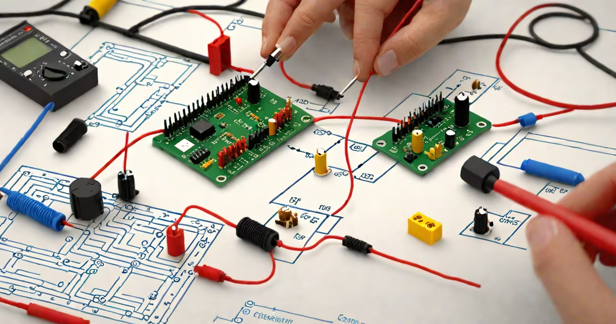
An LDR, or light-dependent resistor, is a passive electronic component whose resistance decreases when exposed to light. It functions as a variable resistor controlled by ambient light levels, making it useful in automatic lighting systems, security sensors, and environmental monitoring devices.
LDRs operate based on photoconductivity. In darkness, their resistance can exceed 1 MΩ. Under bright light, resistance drops to around 1 kΩ. This wide range allows them to interface easily with microcontrollers like Arduino or Raspberry Pi via simple voltage dividers.
For accurate readings, the LDR must be paired with a fixed resistor in a voltage divider configuration. The output voltage across the fixed resistor varies with light intensity and can be read by an analog input pin. Without proper calibration, the sensor may give inconsistent results due to variations in light source color temperature and ambient conditions.
The most common setup uses an LDR in series with a fixed resistor (typically 10 kΩ) between power (VCC) and ground. The midpoint connects to an analog input pin. As light increases, the LDR's resistance drops, increasing the voltage at the midpoint. The microcontroller reads this voltage and converts it into a digital value (0-1023 for 10-bit ADC).
For example, in a dark room, the LDR resistance is high (e.g., 500 kΩ), so most of the voltage drops across it. The voltage at the midpoint is low-close to 0 volts. In bright light, the LDR resistance falls to 1 kΩ, so the voltage at the midpoint approaches VCC (usually 5V). The microcontroller detects this change and triggers actions like turning on a lamp.
Using a 10 kΩ resistor ensures the voltage range stays within the measurable limits of most microcontrollers. A lower-value resistor risks saturating the signal in bright light; a higher value reduces sensitivity in dim conditions.
LDRs come in different spectral sensitivities. Most common types respond best to visible light (400-700 nm), mimicking human eye response. Some are sensitive to infrared (IR) or ultraviolet (UV), but these are less common and require specific filtering.
| Type | Spectral Range | Typical Resistance (Dark) | Typical Resistance (Bright) |
|---|---|---|---|
| Standard CdS LDR | Visible (400-700 nm) | 1 MΩ | 1 kΩ |
| Infrared-sensitive | 700-1100 nm | 500 kΩ | 500 Ω |
| UV-enhanced | 250-400 nm | 2 MΩ | 2 kΩ |
When selecting an LDR, match the spectral response to your environment. A standard CdS LDR works well indoors under incandescent or LED lighting. For outdoor use with sunlight, consider one with broader spectral coverage. IR-sensitive models are used in remote controls or motion detection systems.
One frequent error is assuming the LDR output is linear. Resistance changes logarithmically with light intensity. A reading of 500 lux doesn't produce half the voltage of 1000 lux. This nonlinearity requires calibration or lookup tables for accurate interpretation.
Another issue is environmental interference. LDRs react to heat, humidity, and even dust accumulation. A dirty lens or housing can cause drift. Always clean the sensor surface with a lint-free cloth before deployment.
During testing, I once had an LDR trigger a light at dusk but fail at dawn. The problem wasn't the sensor-it was the sun's angle. Direct sunlight caused saturation. I added a software threshold filter and adjusted the reference voltage to handle edge cases. The system now responds reliably across sunrise to sunset.
To calibrate an LDR, measure its resistance under known light levels. Use a lux meter or standard light source (e.g., 100 lux from a desk lamp). Record the analog input value at each level. Plot the values to create a calibration curve.
For example, with a 10 kΩ fixed resistor and 5V supply: - In complete darkness: analog reading ≈ 0 (voltage ≈ 0V) - At 100 lux: reading ≈ 250 (voltage ≈ 1.2V) - At 1000 lux: reading ≈ 700 (voltage ≈ 3.4V)
Use these points to define thresholds in code. If the reading exceeds 600, assume bright light and turn off a nightlight. This avoids false triggers during twilight.
For better accuracy, implement a moving average filter to smooth out noise. Read the sensor 10 times and take the median. This reduces jitter caused by flickering lights or electrical interference.
LDRs are often combined with relays or transistors to control high-power devices. A small signal from the microcontroller activates a transistor, which switches a 120V AC lamp. This prevents damaging the microcontroller with high-voltage loads.
When building automated systems, pair the LDR with a delay function. Avoid rapid toggling during transitions. Implement a debounce period of 10 seconds to prevent flickering. This improves user experience and reduces wear on mechanical switches.
For advanced setups, integrate LDR data with cloud platforms. Send readings to a dashboard via Wi-Fi. Monitor light levels remotely. This is useful in greenhouses, museums, or smart homes.
Understanding what you work with matters. a solar tracker, knowing how to make an LDR work reliably begins with correct wiring, calibration, and environmental awareness.
With proper setup, an LDR delivers consistent, actionable data. Its simplicity makes it ideal for beginners and a solid base for advanced projects.